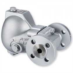
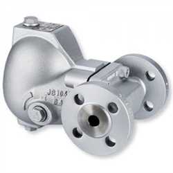
Gestra SRL6-50
BRAND : Gestra
Description
If the level electrode (high or low level limiter) is installed in an isolatable level pot outside the boiler, make sure that the level pot is drained and the connecting lines are rinsed at regular intervals. For this purpose the connecting lines must be shut off and opened at regular intervals and by opening and closing the drain valve the lines and the level pot will be rinsed. The logic unit is designed to be used in conjunction with level switch NRS 1-50 (water level limiter) or level switch NRS 1-51 (high level alarm) to monitor the correct timing and sequence of valve operations. During the rinsing process the level switch jumpers the level electrode, thus preventing the safety or control circuit from opening. The level switch - controlled by the logic unit - also monitors the rinsing and bypass time.
Function
The logic unit monitors the following times and process se - quences: Interval time: This is the time interval at which, depending on the operating mode (24h / 72h boiler operation without constant supervision), the connecting lines have to be rinsed. During operation the standby time is started after the in - terval time has elapsed and the interval time is reset to its initial value (24h/72h). During the standby time the connecting lines must be rinsed. Synchronizing: When valve D or E closes the purging time starts and the interval time is reset to 24h/72h. The purging time can start any time. ...
Details
Description
If the level electrode (high or low level limiter) is installed in an isolatable level pot outside the boiler, make sure that the level pot is drained and the connecting lines are rinsed at regular intervals. For this purpose the connecting lines must be shut off and opened at regular intervals and by opening and closing the drain valve the lines and the level pot will be rinsed. The logic unit is designed to be used in conjunction with level switch NRS 1-50 (water level limiter) or level switch NRS 1-51 (high level alarm) to monitor the correct timing and sequence of valve operations. During the rinsing process the level switch jumpers the level electrode, thus preventing the safety or control circuit from opening. The level switch - controlled by the logic unit - also monitors the rinsing and bypass time.
Function
The logic unit monitors the following times and process se
-
quences:
Interval time: This is the time interval at which, depending
on the operating mode (24h / 72h boiler operation without
constant supervision), the connecting lines have to be rinsed.
During operation the standby time is started after the in
-
terval time has elapsed and the interval time is reset to its
initial value (24h/72h).
During the standby time the connecting lines must be rinsed.
Synchronizing: When valve D or E closes the purging time
starts and the interval time is reset to 24h/72h. The purging
time can start any time. The purging time can also start after
the stand-by time has elapsed.
After the purging time has started the stand-by input of the
level switch NRS 1-50, NRS 1-51 will also be activated.
During the purging time all valves must be opened and
closed in a fixed sequence. The logic unit polls the limit
switches to obtain data on the valve positions and the level
electrode for information on the water level (low level if
electrode is exposed).
If valves D and E are open after the rinsing process and valve
F closed and the level electrode for low water (low level) is
submerged again, the stand-by input of the level switch will
be deactivated.
The stand-by time of the level switch is limited to a maxi
-
mum of 5 minutes. If the stand-by input is not deactivated
by the logic unit during this time, the level switch will open
the safety or control circuit
