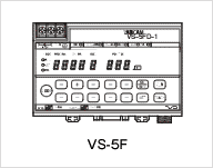
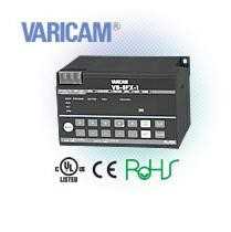
NSD VS-5F-1 VARICAM Cam Switch Output Controller
BRAND : NSD
Model coding
VS-5F[1][2]-[3]
- [1]No. of programs×No. of switch outputs , and others
Details
Model coding
VS-5F[1][2]-[3]
- [1]No. of programs×No. of switch outputs , and others
Code Output code Blank 1 program×24 switches D 8 programs×24 switches, current position BCD output. X 16 programs×40 switches or 32 programs×24 switches, current position BCD output.
- [2]Output system
Code Output system Blank Sink type
- [3]Power supply voltage
Code Specification 1 24VDC
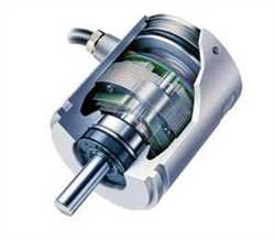
ABSOCODER Basic Configuration

Specification
General specification
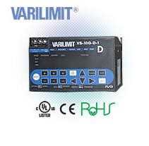
Item Specification Converter model VS-5F-1 VS-5FD-1 VS-5FX-1 Power supply voltage 24VDC Permissible power
voltage range21.6 ? 30VDC Power consumption 10W or less Insulation resistance 20M? or more between external AC power terminals and ground
(by 500 VDC insulation resistance tester)Withstand voltage 500 VAC, 60Hz for 1 minute
between external DC power terminals and groundVibration resistance 20m/s2 10 ? 500Hz, 10cycles of 5 minutes in 3 directions,
conforms to JIS C 0040 standardAmbient operating
temperature0 ? +55? (No freezing)
(Surrounding air temperature rating of 55? maximum)Ambient operating
humidity20 ? 90 %RH (No condensation) Ambient operating
environmentFree from corrosive gases and excessive dust Ambient storage
temperature-10 ? +70? Grounding Must be securely grounded (ground resistance of 100 ohm or less) Construction Inside control panel Mounting Select from two-screw mounting/DIN rail installation/
on-panel mounting using panel mounting fixture VS-K-F.Outside dimension (mm) 130(W)×81(H)×99(D) Mass Approx. 0.7kg Performance Specification
Item Specification Converter model VS-5F-1 VS-5FD-1 VS-5FX-1 Applicable sensor VRE-P028,VRE-P062 Min. setting units 0.5° Number of programs (Panel display) 1 8(0 ? 7) 16
(0 ? 15)32
(0 ? 31)Number of switch outputs 24 24 40 24 Number of multi-dogs 10 times for each switch output (0 ? 9) Position data sampling time
(permissible speed)0.176ms (900 r/min When ON / OFF range is 1 degree) Switch output setting method Numerical setting from the panel or teaching Setting value memory Non-volatile memories (FRAM) Error detection Sensor power error, Sensor error , Memory error , No setting error , Setting impossible error , System error Auxiliary functions Protected switch ? ? ? Setting change
during operation? ? ? Current position value
(BCD, gray code
(720-division))- ? ? Binary speed output - Selectable between current position output and speed output Selectable between current position output and speed output Timing pulse output ? ? ? Motion detection switch Selectable between timing pulse and speed detection output Selectable between timing pulse and speed detection output Selectable between timing pulse and speed detection output Switch output enable ? ? ? Hysteresis ? ? ? Exterminal origin set - - ? Arbitrary pulse output ? ? ? Current position HOLD - ? ? Error cancel ? ? ? Password ? ? ? Communication function Serial (RS-232C) communication (setting value saving or loading, monitoring, operation commands)
- Connection by Mitsubishi-only protocol/MELSEC-A protocol
- Connection with angle display unit (NDP) is also possible
- Connection by OMRON-only protocol
- Connection with touch panel is possible (VARIMONI)
Connection of
an external display unitI/O connection - ? ? Communication
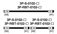
connection? ? ? Max. sensor
cable lengthStandard 100m Robotic(RBT) 100m I/O spcification
Item VS-5F-1 VS-5FD-1 VS-5FX-1 Description Input
signalsProgram No. - 3 points 4/5 points Inputs the exteral program No. Current position HOLD - 1 point - Used to prevent the current position value from changing when controller reading occurs. Current position HOLD or
external origin set- - 1 point Input to prevent current position from changing or for origin setting. Error cancel 1 point 1 point 1 point Input to cancel an error display. Switch output enable 1 point 1 point 1 point Switch signal will be output only upon the input of this signal. Output
signalsSwitch output /
Arbitrary pulse output24 points 24 points 40/24 points ON/OFF signal will be output based on the switch setting value, or pulse signal
will be output based on equally dividing a single rotation (division selectable from 1 ? 360).Timing pulse /
Motion detection switch1 point 2 points 1 point 60, 180 or 360 pulse signals will be output per rotation, or ON/OFF signal will be output based on the speed setting value. System ready 1 point 1 point 1 point Outputs when controller and sensor are functioning normally. Program No. - 3 points 4/5 points The currently selected Program No. is output. Current position value
(BCD, gray code
(720-division)) /
Speed Binary output- 11 points 11 points Current position (3-digit BCD + 0.5-deg display) signal will be output, or rotational speed will be output in binary code. Latch pulse - 1 point 1 point Outputs a timing signal which ensures that the current position is read in a stable condition. Item Input specifications Item Output Specifications Input signals Program No.
External origin set
Current position HOLD
Error cancel
Switch output enableOutput signals Switch output or arbitrary pulse
Program No. Sysytem readyMotion detection switch or timing pulse Current position value (BCD, gray code (720-division)) or speed (binary)
latch pulseInput circuit DC input, photo-coupler isolation Output circuit Transistor (open-collector), photo-coupler isolation Input logic Negative logic Output logic Negative logic Negative logic Positive logic*1 Rated input voltage 24VDC Other Suggested Products
Products