EKF CCE-PUNK I/O Companion Board
BRAND : EKF
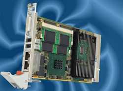
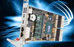
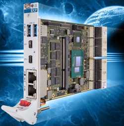
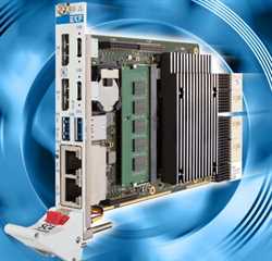
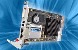
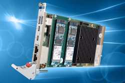
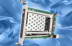
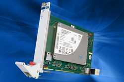
Available as a mezzanine companion board to the CCD-CALYPSO CPU card, the CCEPUNK is provided with high-speed communication channels such as FireWire and USB, and common legacy I/O ports as well. Interconnection between the CCE-PUNK I/O module and the CPU carrier board is achieved by several expansion connectors, which comprise the PCIe (PCI Express), LPC (Low Pin Count) and ATA/IDE interfaces. As an option, the CCE-PUNK is available with a rugged on-board 2.5-inch hard disk drive (1.8-inch SSD/HDD as a mezzanine module
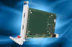
The CCE-PUNK will be attached on top of the CPU board, and shares its front panel typically with the host CPU carrier board (8HP front panel width in total). In addition to its front panel I/O connectors, the CCE-PUNK has been designed also for rear I/O and therefore requires a non-bussed single-slot P1/P2 backplane in addition to the CompactPCI bus. However, if front panel I/O is solely needed, the J1/J2 connectors may be omitted as an option.
The CCE-PUNK communicates with the host CPU by means of 3 expansion connectors: P1 (LPC), P21 (PATA/IDE), and P30 (PCI Express). The LPC (Low Pin Count) is a multiplexed ISA bus, enabling the super-I/O controller chip to emulate the legacy I/O interfaces. Among these are the classic parallel (printer) and serial (COM) ports. The Parallel ATA/IDE interface is still essential for embedded applications, due to the availability of ATA CompactFlash cards and 1.8-in...
Details
Available as a mezzanine companion board to the CCD-CALYPSO CPU card, the CCEPUNK is provided with high-speed communication channels such as FireWire and USB, and common legacy I/O ports as well. Interconnection between the CCE-PUNK I/O module and the CPU carrier board is achieved by several expansion connectors, which comprise the PCIe (PCI Express), LPC (Low Pin Count) and ATA/IDE interfaces. As an option, the CCE-PUNK is available with a rugged on-board 2.5-inch hard disk drive (1.8-inch SSD/HDD as a mezzanine module
The CCE-PUNK will be attached on top of the CPU board, and shares its front panel typically with the host CPU carrier board (8HP front panel width in total). In addition to its front panel I/O connectors, the CCE-PUNK has been designed also for rear I/O and therefore requires a non-bussed single-slot P1/P2 backplane in addition to the CompactPCI bus. However, if front panel I/O is solely needed, the J1/J2 connectors may be omitted as an option.
The CCE-PUNK communicates with the host CPU by means of 3 expansion connectors: P1 (LPC), P21 (PATA/IDE), and P30 (PCI Express). The LPC (Low Pin Count) is a multiplexed ISA bus, enabling the super-I/O controller chip to emulate the legacy I/O interfaces. Among these are the classic parallel (printer) and serial (COM) ports. The Parallel ATA/IDE interface is still essential for embedded applications, due to the availability of ATA CompactFlash cards and 1.8-inch hard disks with an ATA/IDE compatible I/F only. Optionally, the CCEPUNK can be equipped with either a CompactFlash mezzanine module, or a robust 2.5-inch hard disk drive, particularly suited for use in a rugged environment. A mezzanine module is also available which carries an 1.8-inch drive, as an alternative. The CCE-PUNK fits on the top side of the CCD-CALYPSO CPU board, which is on the right side when looking at the front panel of the boards inserted into a CPCI rack.
In addition to front panel I/O, some of the
interfaces of the CCE-PUNK are available for
rear I/O across the connectors J1/P1 and
J2/P2. A suitable rear I/O transition module
such as the CCZ-RIO would be required in
addition to gain access to the I/O ports from
the systems back panel.
Several I/O functions are also directly
available by on-board headers on the CCEPUNK, mainly the IDE interface. Other onboard connectors are only stuffed as an
option, however.
If equipped with the rear I/O connectors
J1/J2, the CCE-PUNK must be inserted on a
slot outside of the CompactPCI backplane. A
single slot rear I/O P1/P2 backplane should
be present in the system rack at the CCE
reserved slot. Most EKF systems have the
CPCI busprint justified to the left margin of
the 19-inch rack, with the system slot (CPU
slot) orientated to the right end of the
backplane. Following next to the right side,
the CCE-PUNK should be placed in between
the remaining free mounting space.
