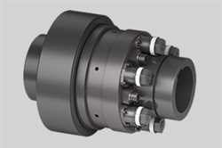
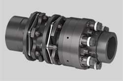
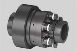
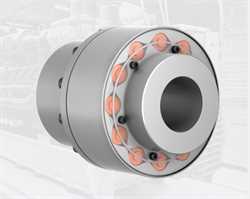
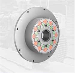
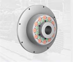
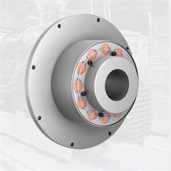
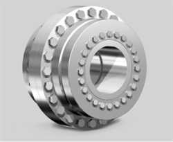
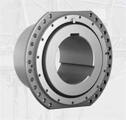
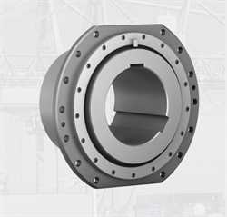
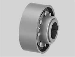
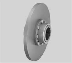
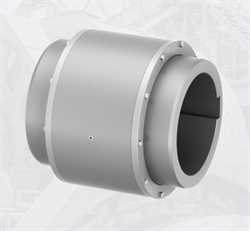
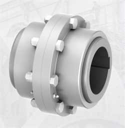
Ringfeder TNZ ZCAZ/TNZ ZCBZ Gear Coupling
BRAND : Ringfeder
Standard hubs and spacer
The ...
Details
Standard hubs and spacer
The coupling model RINGFEDER® TNZ ZCAZ is complemented with a spacer that is mounted between the sleeves of a TNZ ZCA coupling by using ?tted bolts. The spacer serves to accommodate larger distances between the shafts ends, and can be mounted and dismounted radially without having to move the connected machines.
Unlike the TNZ ZCAZ, the coupling RINGFEDER® TNZ ZCBZ is equipped with a bolt-on O-ring carrier which facilitates installation by changing the mounting sequence. The coupling model TNZ ZCBZ is complemented with a spacer that is mounted between the sleeves of a TNZ ZCB coupling by using ?tted bolts.
Characteristics
General features
- Torsionally rigid gear coupling made of high-quality steel
- Very compact design results in a high-power density
- Compensates for angular, radial and axial shaft offset
- Suitable for use in temperatures up to +120 °C if special seals are used
- Available with split sleeve (ZCA / ZCB - ZCA model range also available in ZCB design) and single-piece sleeve (ZCH)
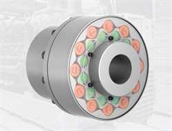
- The elastic O-Ring can be replaced without having to move the coupled machines
- Bores up to 270 mm
- Torques up to TKn = 195,000 Nm / TKmax = 390,000 Nm
- Speeds up to nmax = 6,000 rpm
General description
The RINGFEDER® TNZ coupling is a torsionally rigid twin cardanic gear coupling.
Toothing
The coupling housings have a straight internal toothing whilst the hubs have an external toothing with a chased variable radius. As a result, the hubs can move spatially within the housing and thus compensate angular, radial and axial shaft misalignment of the adjoined shaft ends within specified tolerances. Depending on coupling type and size, the standard toothing permits an angular misalignment of up to 0.5 degrees per toothing-plane and an axial movement of several millimetres. The max. possible radial shaft displacement is dependent on the distance between the two toothing planes. Other toothing geometries can be used for further specific applications.
Materials
High-grade tooth profiles and grease with ultra high-pressure additives guarantee low-restoring forces and a long serviceable life. The material used is forged steel with an apparent yielding point of at least 335 N/mm2. Special materials can be used for further specific applications. Sealing is carried out using O-Rings of synthetic rubber. The housings are centred and held together by fit-bolts and self-locking nuts.
Temperature
The use of special seals permits the temperature limit to be raised to 120 °C.
Balance
At peripheral speeds upwards of 30 m/s it is advisable to dynamically balance the coupling.
Special applications
If greater misalignments are anticipated at higher speeds and torques, an examination is necessary, performed with the assistance of a special computing programme. This is independent of the determined size. The value TKmax may not be exceeded in any state of operation (start-up, electrical short circuit, blocking, etc.).
Tolerances and standards
The bore tolerance is ISO H7, if not differently ordered. The bore diameters listed refer to keyways to DIN 6885-1.
