Mts Sensor MH SIL2 Mobile Hydraulic Position Sensor
BRAND : Mts Sensor
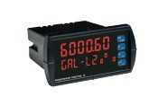
Output
Signal characteristic Continuously analog output restricted by noise or A/D converter of control unit
Voltage 0.5…4.5 VDC with failure signal < 0.5 VDC LO > 4.5 VDC HI
Current 4…20 mA with failure signal < 4.0 mA LO > 20 mA HI
Measured value Position
Measurement parameters
Resolution Typ. 0.1 mm
Power uptime Typ. 250 ms
Linearity 0050…0250 mm 0255…2000 mm 2005…2500 mm
? ±0.1 mm ±0.04 % (F.S.) ? ±0.8 mm
Hysteresis ±0.1 mm
Internal sample rate 1 ms
Setpoint tolerance ? 1 mm
Operating conditions
Operating temperature electronics ?40…+100 °C
Storage temperature ?20…+65 °C
Fluid temperature ?30…+85 °C
Humidity EN 60068-2-30, 90 % rel. humidity, no condensation
Ingress protection – M12 connector EN 60529 – IP69K (correctly fitted)
Ingress protection – Sensor housing EN 60529 – IP67
Shock test IEC 60068-2-27, 100 g (6 ms) single shock, 50 g (11 ms) at 1000 shocks per axis
Vibration test IEC 60068-2-64, 20 g (r.m.s.) Ø 10 mm pressure pipe (10…2000 Hz) – resonance frequencies excluded
EMC test UNECE Regulation 10 Rev 5: Electromagnetic Compatibility
ISO 14982 Agricultural and forest machines
EN 13309 Construction machines
Immunity: ISO 11452-2 (200 V/m Antenna), ISO 11452-4 (200 mA BCI)
Emissions: CISPR 25
Transiente Impulses: ISO 7637-1/2
E.S.D.: ISO/TR 10605
The sensor meets the requirem...
Details
Output
Signal characteristic Continuously analog output restricted by noise or A/D converter of control unit
Voltage 0.5…4.5 VDC with failure signal < 0.5 VDC LO > 4.5 VDC HI
Current 4…20 mA with failure signal < 4.0 mA LO > 20 mA HI
Measured value Position
Measurement parameters
Resolution Typ. 0.1 mm
Power uptime Typ. 250 ms
Linearity 0050…0250 mm 0255…2000 mm 2005…2500 mm
? ±0.1 mm ±0.04 % (F.S.) ? ±0.8 mm
Hysteresis ±0.1 mm
Internal sample rate 1 ms
Setpoint tolerance ? 1 mm
Operating conditions
Operating temperature electronics ?40…+100 °C
Storage temperature ?20…+65 °C
Fluid temperature ?30…+85 °C
Humidity EN 60068-2-30, 90 % rel. humidity, no condensation
Ingress protection – M12 connector EN 60529 – IP69K (correctly fitted)
Ingress protection – Sensor housing EN 60529 – IP67
Shock test IEC 60068-2-27, 100 g (6 ms) single shock, 50 g (11 ms) at 1000 shocks per axis
Vibration test IEC 60068-2-64, 20 g (r.m.s.) Ø 10 mm pressure pipe (10…2000 Hz) – resonance frequencies excluded
EMC test UNECE Regulation 10 Rev 5: Electromagnetic Compatibility
ISO 14982 Agricultural and forest machines
EN 13309 Construction machines
Immunity: ISO 11452-2 (200 V/m Antenna), ISO 11452-4 (200 mA BCI)
Emissions: CISPR 25
Transiente Impulses: ISO 7637-1/2
E.S.D.: ISO/TR 10605
The sensor meets the requirements of the EC directives and is marked with
Pressure (according to DIN EN ISO 19879)* Ø 10 mm pressure pipe
PN (nominal operating) 350 bar
Pmax (max. overload) 450 bar
Pstatic (proof pressure) 625 bar
Design / Material
Sensor electronics housing Stainless steel 1.4305 (AISI 303)
Sealing O-ring 40.87 × 3.53 mm NBR 80, back-up ring 42.6 × 48 × 1.4 PTFE
Sensor rod Stainless steel 1.4306 (AISI 304L)
M12 connector insert Material: polyamide reinforces; O-ring 7 × 1.35 mm NBR 70; pins: brass with gold plated pins
M12 flange Brass nickel-plated with O-ring 13 × 1.6 NBR 70
Stroke length 50…2500 mm
Mechanical mounting
Mounting position Any
Mounting instruction Please consult the technical drawings
Electrical installation
Connector M12 male connector
Supply voltage 12 VDC (8…32 VDC) 24 VDC (16…32 VDC)
Current consumption Typ. < 100 mA Typ. < 50 mA
Load (output VDC) RL
> 10 k? RL > 10 k?
Load current (output VDC) Typ. 0.5 mA Typ. 0.5 mA
Load (output mA) RL
< 250 ? RL
< 500 ?
Inrush current Max. 2.5 A/2 ms Max. 4.5 A / 2 ms
Supply voltage ripple < 1 % PP
Power drain < 1 W
Over voltage protection (GND - VDC) Up to +36 VDC
Polarity protection (GND - VDC) Up to ?36 VDC
Insulation Resistance R ? 10 M? @ 60 sec
Electric strength 500 VDC (DC GND to chassis GND)
*/ According to calculations under use of the FKM guideline
Cycles Ø 10 mm sensor rod
Dynamic pressure: < 2 × 10⁶
pressure cycles 350 bar
Static pressure: < 2 × 10⁴
pressure cycles 450 bar
Proof pressure: Maximum 5 minutes testing time for cylinder pressure test 625 bar