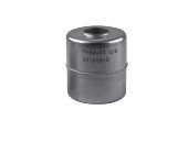
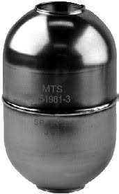
Mts Sensor EP-0-0500M-D34-1-V03 Position Sensor
BRAND : Mts Sensor
Drawings are for reference only, contact applications engineering for tolerance specific information.
A robust aluminum extrusion forms the sensor housing containing the sensing element and electronics. The position magnet moves along
the top of the profile extrusion housing.
MODEL EP
Figure 4.
M12 connector
29 mm
(1.1 in.)
19 mm
(0.75 in.)
13 mm (0.5 in.)
40 mm
(1.6 in.)
14.6 mm (0.57 in.)
Mounting clamp
49 mm
(1.9 in.)
50 mm (1.97 in.)
68 mm (2.68 in.)
Mounting
clamp
5-pin (M12) or
8-pin (M12)
Stroke length
(See ‘Ordering Information’ for stroke length details)
84 mm
(3.3 in.)
Dead zone
Beginning of stroke - Null position
Ball-jointed arm (M5 thread, vertical 18? / horizontal 360?)
Captive-sliding magnet, Style S part no.: 252182
E-Series model EP sensor dimension reference (Shown with Style S captive-sliding magnet)
Details
Drawings are for reference only, contact applications engineering for tolerance specific information.
A robust aluminum extrusion forms the sensor housing containing the sensing element and electronics. The position magnet moves along
the top of the profile extrusion housing.
MODEL EP
Figure 4.
M12 connector
29 mm
(1.1 in.)
19 mm
(0.75 in.)
13 mm (0.5 in.)
40 mm
(1.6 in.)
14.6 mm (0.57 in.)
Mounting clamp
49 mm
(1.9 in.)
50 mm (1.97 in.)
68 mm (2.68 in.)
Mounting
clamp
5-pin (M12) or
8-pin (M12)
Stroke length
(See ‘Ordering Information’ for stroke length details)
84 mm
(3.3 in.)
Dead zone
Beginning of stroke - Null position
Ball-jointed arm (M5 thread, vertical 18? / horizontal 360?)
Captive-sliding magnet, Style S part no.: 252182
E-Series model EP sensor dimension reference (Shown with Style S captive-sliding magnet)
