Details
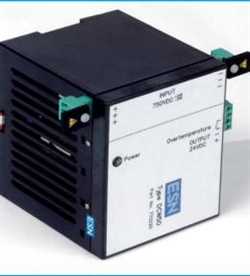
Potential monitoring device as per DIN EN 50122 part 1 / VDE 0115 part 3
As protection from dangerous body currents generated from contact voltages/tapping voltages,
maximum voltages have been stipulated depending on the effect time.
|
|
Technical Data
|
|
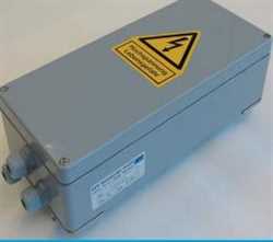
Dimensions
|
W / H / D 150 / 73 / 113 mm
|
|
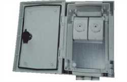
Housing material
|
Terminal board: polycarbonate
|
|
|
lower section: ABS
|
|
Fastening
|
2 drilled holes as per drilling tem-
|
|
|
plate Standard support rails as per
|
|
|
DIN
EN 50022
|
|
Protection
|
Housing: IP 40; terminals: IP 10
|
|
Connections
|
2 x 2.5 mm2 solid to DIN
46288 or
|
|
|
2
x 1.5 mm2
|
|
Ambient temp.
|
- 20°C to +
60°C
|
|
Power supply
|
AC 19.2 ... 253 V,
50 – 60 Hz, ? 5.5
|
|
|
VA
|
|
|
DC
19.2 ... 253 V, ? 2.5 W
|
|
Measuring input
|
? 1500 V, continuous; resistance:
|
|
|
approx. 2 M?
|
|
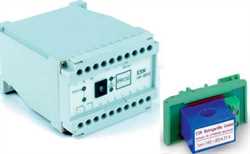
Relay outputs
|
2 change-over contacts (u), poten-
|
|
|
tial-free
|
|
|
voltage current cos ?
|
|
|
AC 250 V4.0 A > 0.7
|
|
|
DC 120 V 1.0 A ohmic load
|
|
Displays
|
Network LED green
|
|
|
K1: LED yellow
|
|
|
K2: LED yellow
|
|
|
voltage level: bar graph array
|
|
Test voltage
|
Supply voltage - measuring voltage
|
|
|
outputs: 6 kVe?
|
|
Input voltage
|
DC 50 V <
UM <
DC 90 V
|
|
|
K1 switches after 295 ... 299 s
|
|
|
(workshop)
|
|
|
DC
100 V < UM <
DC 140 V
|
|
|
K1 and K2 switch after 295 ...
299 s
|
|
|
UM > DC 140 V
|
|
|
K1 and K2 switch jointly as per
|
|
|
diagram
|
|
|
UM > DC 660 V
|
|
|
K1 and K2 switch after max. 30 ms
|
|
|
AC
25 V < UM <
AC 40 V
|
|
|
K1 switches after 295 ... 299 s
|
|
|
(workshop)
|
|
|
AC
50 V < UM <
AC 70 V
|
|
|
K1 and K2 switch after 295 ...
299 s
|
|
|
UM > AC 70 V
|
|
|
K1 and K2 switch jointly as per diagram
|
|
|
UM > AC 842 V
|
|
|
K1 and K2 switch after max. 30 ms
|
|
Diagram
|
see overleaf
|
|
Ordering Information
|
|
Type 8521
|
Order No. 210100
|